Lab 2
Lab 2 - ROS development and Kinematics
List of Deliverables
Answers to exercise questions in Q&A form in the report
Screenshot of camera image view
Screenshot of code that acquires and sends images
Video of duckiebot in part 2
Link to rosbag file
The animated plot of odometry information stored in the bag file
Report
Introduction
In this exercise, we learned how to move duckiebot for a multi-state task. The following report will explain the steps we took in order to do this. I will include the procedures we went through, and also the challenges we faced, and the takeaways from each part.
I intend to write this report such that it can be like a small cheatsheet for me to visit later for summarizing the concepts I need to know about ROS, odometry, and kinematics, tips and tricks, and where to find what, etc. Questions asked in the exercise documentation are answered in Q&A form.
ROS Concepts Cheatsheet
ROS is a flexible framework for writing robot software. It consists of several concepts such as nodes, topics, services, messages, and bags. These segments work together and help us build and design complex robotic systems.
More information about ros in duckietown: Introduction to ROS .
More information about ros concepts in general: ROS/Tutorials.
Node
A Node is an individual processing unit in ROS. Nodes are responsible for performing a specific task. Nodes can represent different parts of a robotic system(sensors, actuators, controllers, etc). they communicate with each other by sending and receiving messages through Topics. Nodes can be either publishers or subscribers. It means they can send data, or receive data.
A publisher can be defined as:
pub = rospy.Publisher('topic_name', message_type, queue_size=10)
We can use .pub() method to publish data to a topic from a node.
Subscriber = rospy.Subscribe('topic_name', message_type, callback)
We can access the data that the subscriber receives with the callback function.
Note: I figured it was necessary to read in detail about what the correct topic_name and message type are whenever I needed to define a publisher or subscriber.
The command below can show the list of active nodes.
$rosnode list
We can also find information about nodes in the dashboard.
Note: This comes in handy when a node is not working as expected and you want to make sure if it is active or not at all, before debugging it, which I faced a few times in this exercise.
we need to define publishers and subscribers in different parts of this exercise.
Topic
Topics allow nodes to communicate with each other. Nodes can send or receive data through topics. Topics have specific message types, which specify the type of data being transmitted between nodes.
We can use the command line to interact with rostopics. The command below gives the list of current topics:
$rostopic list
Note: This comes in handy when you are not sure which topic to use for a particular task. In this case, one thing to do is to search among the list of topics, and find one that seems to do the task you are looking for, and then read more about the topic you have found in detail to figure out if it is a suitable topic for your task.
Service
services are a way for Nodes to request actions from other nodes in ROS. Service is defined by a unique name, a request message type, and a response message type. Unlike Topics, which allow for continuous data exchange, Services are designed for one-time requests. When a node requests a Service, it blocks until the Service has completed and returned a response.
Again, $rosservice list can give us the list of all services available.
In this exercise, we needed to use services for led light color change.
Message
Messages are the data structures used for communication between nodes in ROS. They define the structure of the data being transmitted through Topics. Topics are typed by ros message type, and nodes can only send and receive messages with matching type.
Bag
Bags are a way to store and analyze the data from ROS topics for offline analysis.
Ros bag is a file that contains data transmitted over topics. This data can be analyzed for debugging. In this exercise, we needed to store the odometry data in the rosbag in order to see how our robot perceives its movements.
Camera Subscriber
1- How can you store your robot’s name in a variable instead of hardcoding it?
I found these ways to do it:
robot_name =os.environ['VEHICLE_NAME']
robot_name = rospy.get_namespace().strip("/")
This allows us to be able to run the code on other robots as well.
After searching for a while, I read about compressedImage in ROS tutorials for this part of the exercise.
CompressedImage is the message type of the topic that contains the images. The topic that the images are published on is: ~/camera_node/image/compressed
We need to read data on this topic. Therefore, we define a subscribing node to this topic and read the data from it.
The callback function is called when the subscriber node runs, so we should put our work in this function.
We read the data, but since its type is compressedImage, if we print the shape, it returns different values each time. We use the bgr_from_jpg function to decode the image, and now we can print out the shape. Once we do this, we modify and publish the image using a publisher.
We publish the image on the ~modified_img topic.
The code and the details are:
#!/usr/bin/env python3
# Code adapted from [4], specifically I used the file at
# https://github.com/duckietown/sim-duckiebot-lanefollowing-demo/blob/master/custom_line_detector/src/line_detector_node.py
from cv_bridge import CvBridge
from duckietown.dtros import DTROS, NodeType
from duckietown_utils.jpg import bgr_from_jpg
from sensor_msgs.msg import CompressedImage, Image
import os
import rospy
class CameraSubscriberNode(DTROS):
"""
CameraSubscriberNode reads images from the DuckieBot camera, switches the
blue and green channels, and then publishes these images on a new topic.
Configuration:
Subscribers:
~/camera_node/image/compressed
Publishers:
~/modified_img
"""
def __init__(self, node_name):
# initialize the DTROS parent class
super(CameraSubscriberNode, self).__init__(node_name=node_name, node_type=NodeType.GENERIC)
# Subscribe to the image topic to receive incoming images
rospy.loginfo("Initializing Camera Subscriber Node")
self.sub = rospy.Subscriber(
'camera_topic', CompressedImage, self.callback,
)
# Construct the topic along which to publish our modified images
self.bridge = CvBridge()
self.pub = rospy.Publisher(
'~modified_img', Image, queue_size=10,
)
def callback(self, img_msg):
# Read the incoming image data, decode it into a BGR image, and print
# its shape
data = bgr_from_jpg(img_msg.data)
rospy.loginfo(f"Image dimensions: {data.shape}")
# Switch the blue and green channels
b, g = data[:, :, 0], data[:, :, 1]
new_data = data.copy()
new_data[:, :, 1] = b
new_data[:, :, 0] = g
# Convert the cv2 image to an image message for use with rospy
img_msg_out = self.bridge.cv2_to_imgmsg(new_data, "bgr8")
img_msg_out.header.stamp = img_msg.header.stamp
# Send the modified image in a message along the ~/modified_img topic
self.pub.publish(img_msg_out)
if __name__ == '__main__':
node = CameraSubscriberNode(node_name='camera_subscriber_node')
rospy.spin()
The size of the image and the screenshot of the image is shown in Figure 1.
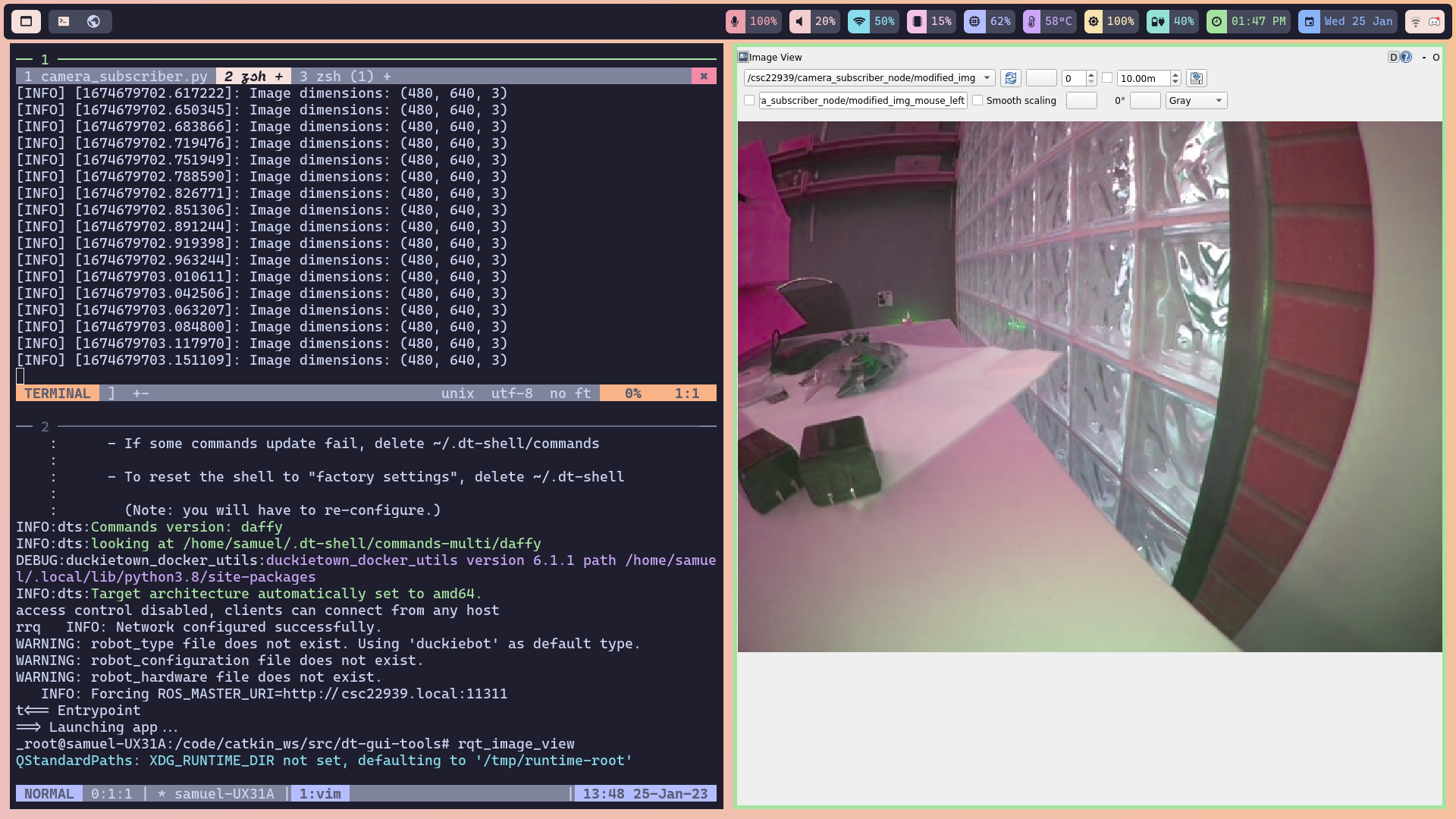
Figure 1: image size and modified camera image
Odometry (route measurement)
I used the MOOC on self-driving cars to understand concepts of kinematics and odometry for this part. The presentations of this MOOC are referenced heavily in the following parts. I also used duckietown learning resources on Available Educational Resources – Duckietown.
2- What is the relation between your initial robot frame and the world frame? How do you transform between them? How do you convert the location and theta at the initial robot frame to the world frame?
If we denote a point in the robot frame with D^r, and denote a point in the world frame with D^w, we can transform between them using a rotation matrix as shown in Figure 2.
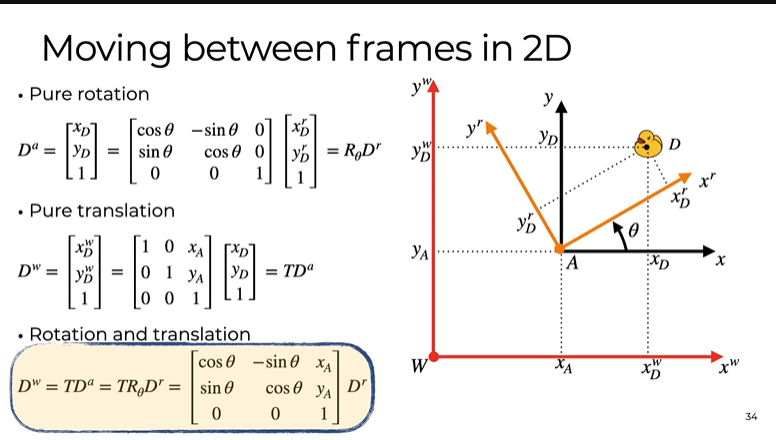
Figure 2: moving between world frame and robot frame
If we follow the above transform and make some assumptions about the robot, we can express the vehicle velocity(which can help us indicate the position of the vehicle in the future) based on the angular velocities of the wheels(which ultimately, are the commands we send to the robot)
Therefore, we can map the pose to wheel commands(this is called forward kinematics!) This is how we can estimate the next position of the robot. The formulas for forward kinematics are shown below in figure 3.
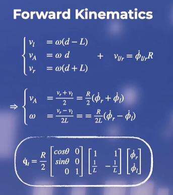
Figure 3: Forward Kinematics
On the other hand, inverse kinematics helps us ask this question:
If we want the robot to move in a certain way, what commands should we send to the wheels?
It means it can map the desired vehicle velocity(which can indicate the desired position) to the angular velocities (commands). This is how we can control the robot. (Our goal in this exercise)
The formulas for inverse kinematics are shown in figure 3.
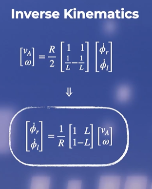
Figure 4: Inverse Kinematics
The robots need to know where they are in the world frame. Now, the question is, how can we update the robot pose using these formulas?
Kinematics help us update the pose. However, we need to know the wheel's angular velocities and the traveled distance by each wheel. It can be calculated as shown below in figure 5.
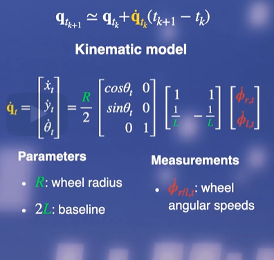
Figure 5: updating the pose estimate based on kinematics formulas
We also need the parameters R and L.
They can be found using the code below:
self.R = rospy.get_param(
f'/{self.veh}/kinematics_node/radius',
0.318,
) # meters, the default value of wheel radius
self.baseline = rospy.get_param(
f'/{self.veh}/kinematics_node/baseline', 0.1
) # meters, the default value of the baseline
Note: rospy.get_param() is a useful method that can give us the value of the parameters that we are looking for.
We can continue to derive the necessary formulas:
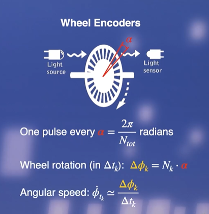
Figure 6: Wheel Encoders
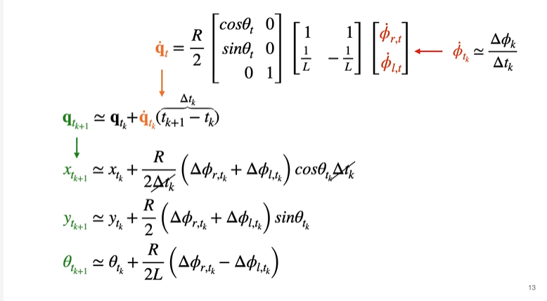
Figure 7: updating the pose estimate formula
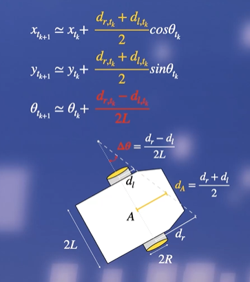
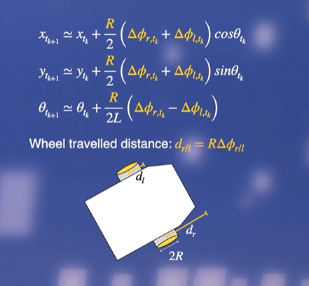
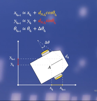
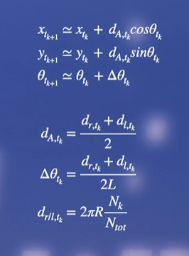
Figure 8: simplifying and deriving the pose update formulas, based on number of ticks in the wheels.
We count the pulses from the encoders, derive the rotation [of each wheel], and then multiply by the radius of each wheel. The second step is to transform the wheel displacements into the linear and angular displacements of the robot reference frame. The final step is to represent the displacement in the world frame and add the increments to the previous estimates.
2- How did you keep track of the angle rotated? How did you estimate/track the angles your DuckieBot has traveled?
dl and dr are the changes to the rotation for the left and right wheels.
~/left_wheel_enocder_node/tick
~/right_wheel_enocder_node/tick
These topics tell us the current tick.
So by having the current tick and the previous tick, we can calculate the change in rotation for both wheels. This is calculated using the delta_phi function in the code.
from duckietown_msgs.msg import WheelEncoderStamped
import numpy as np
# This code is taken and adapted from [2]
def delta_phi(encoder_msg: WheelEncoderStamped, prev_ticks):
"""
Calculate the change in wheel rotation dl/dr based on the incoming
message which describes the current tick reading and the previous number of
ticks read.
These messages can be read from the topics:
~/left_wheel_enocder_node/tick
~/right_wheel_enocder_node/tick
"""
ticks = encoder_msg.data # Current number of ticks
delta_ticks = ticks - prev_ticks
n_total = encoder_msg.resolution # Total number of ticks per full rotation
alpha = 2 * np.pi / n_total
delta_phi = alpha * delta_ticks
return delta_phi, ticks
Straight Line Task
3- Which topic(s) did you use to make the robot move?
We said that in inverse kinematics, we can map the desired vehicle velocity(which can indicate the desired position eventually) to the angular velocities (commands). This is how we can control the robot.
Commands are angular velocities, and the known variables are v and omega(desired vehicle velocity).
There is a topic that skips the calculations in inverse kinematics and allows us to indicate v and omega directly.
The topic we use to make the robot move is
~/joy_mapper_node/car_cmd
The message type of this topic is:
duckietown_msgs/msgs/Twist2DStamped
This message contains v and omega, the vehicle velocities.
Therefore, in order to make the robot move in a straight line, we need to create a publisher node and publish the desired v, and omega=0.
4- How did you figure out the topic that could make the motor move?
Honestly, it was a lot of searching in codebases, and getting help from my teammate, Samuel.
I realized that ROS command line commands such as rostopic list can be useful in such cases when you are looking for a specific topic. You can find the information about that topic using rostopic info topic_name can give you information about the topic.
5- Which speed are you using? What happens if you increase/decrease the speed?
In the code, we set v=0.4.
Lower speeds seem to help the robot to predict its location more accurately.
6- Can you explain why there is a difference between the actual and desired Location?
Kinematics formulas are derived based on some assumptions which might not be true in the real world
Wheels are assumed to be identical which might not be the case. It is also assumed that there is no slipping and skidding. Rigid body rotation is another assumption, that might be violated in the real world. These reasons can cause the actual and the desired location to be different.
Rotation Task
7- Which topic(s) did you use to make the robot rotate?
As explained above, the topic we use to make the robot move is:
~/joy_mapper_node/car_cmd
The message type of this topic is:
duckietown_msgs/msgs/Twist2DStamped
This message contains v and omega, the vehicle velocities.
Therefore, in order to make the robot rotate, we need to create a publisher node and publish the desired omega.
8- Does your program exit properly after you finish all the above tasks? Is it still
running even if you shut down the program? If this is the case, think about how to
resolve this issue.
Shutting down the nodes can be done with the following code. It is used in encoder_pose_node.py file, for part two of the exercise to make sure all nodes are shutdown at the end of the task.
# For shutting down nodes
shutdown_cmd_topic = f"/{self.veh}/shutdown"
self.pub_shutdown_cmd = rospy.Publisher(shutdown_cmd_topic, Empty, queue_size=1)
# Signal shutdown to remaining active nodes
self.pub_shutdown_cmd.publish(Empty())
rospy.signal_shutdown("done!")
LED light Color
We need to define a service to control the LED color. Service enables communication between nodes.
To write a service, we need to indicate a name for the service. We also need a callback function which in this case is ChangePattern. This function allows changing the duckiebot LEDs.
Then we need to define a service proxy, and call the service using that service proxy to change the led.
Duckiebot has a service for this task, that we used for this exercise.
The code will be:
#!/usr/bin/env python3
# Adapted from [1]
from duckietown.dtros import DTROS
from duckietown_msgs.srv import ChangePattern
from duckietown_msgs.srv import ChangePatternResponse
from std_msgs.msg import String, Empty
import rospy
import time
class LightServiceNode(DTROS):
"""
LightServiceNode implements a service for changing the colours of the the
Duckiebot LEDs. All LEDs are kept the same colour.
Configuration:
Subscribers:
~/shutdown (:obj:`Empty`)
Services:
~/light_service_node/light_change (:obj:`ChangePattern`)
"""
def __init__(self, node_name):
# Initialize the DTROS parent class
super(LightServiceNode, self).__init__(node_name=node_name)
self.veh_name = rospy.get_namespace().strip("/")
# Duckiebots already have a service for changing LED colours, use that
# service to change the colours when users call this node's service
self._led_service = f"/{self.veh_name}/led_emitter_node/set_pattern"
rospy.wait_for_service(self._led_service)
self._embedded_svc = rospy.ServiceProxy(self._led_service, ChangePattern)
# Subscribe to a shutdown notification topic: when we get a message on
# this topic, shut down the node.
shutdown_cmd_topic = f"/{self.veh_name}/shutdown"
rospy.Subscriber(
shutdown_cmd_topic, Empty, self._shutdown, queue_size=1,
)
# Create the service for changing the LED colours
self._svc = rospy.Service(
f"{node_name}/light_change",
ChangePattern,
self._change_light,
)
# Specify the legal colours which the LEDs can be changed to
self._legal_colours = ["RED", "GREEN", "WHITE", "BLUE", "LIGHT_OFF"]
self.log("light_service_node initialized.")
def _shutdown(self, msg: Empty):
"""
Performs the shutdown routine of the node
"""
rospy.signal_shutdown("light_service_node: shutting down...")
def _change_light(self, colour: ChangePattern):
"""
Changes the LED colours of the Duckiebot
"""
if colour.pattern_name.data not in self._legal_colours:
rospy.loginfo(f"colour should be in {self._legal_colours} " +
f"but got {colour}")
try:
# Change the colour of the LEDs
self._embedded_svc(colour.pattern_name)
except rospy.ServiceException as e:
rospy.logwarn("exception when changing LED colours: ", + str(e))
# Tell the client that we received their request
return ChangePatternResponse()
if __name__ == "__main__":
led_emitter_node = LightServiceNode(node_name="light_service_node")
rospy.spin()
The Final Multi-State Task
Video 1: video of the robot performing the mutli-state task.
9- What is the final location of your robot as shown in your odometry reading? Is it close to your robot’s actual physical location in the mat world frame?
Video 1 shows the robot performing the multi-state task. The robot does not behave exactly as we have told it to!
Some of the reasons are explained in question 6.
Some other reasons are explained below:
We are using an open loop control for this exercise. It means that the controller gives commands only, so it is one direction flow. This is a simple and convenient approach, but might not be efficient especially when the task becomes more complex. If we had feedback from the sensors, we could adjust the commands better, which is called a closed-loop control approach.
Dead reckoning is also another issue. It means updating our estimates based on previous estimates, which results in the accumulation of errors.
In summary, there is a drift in our estimate in time due to the accumulation of numerical slipping, skidding, and calibration imprecision errors.
Working with ROS Bags
We should store the robot’s estimated pose of the world frame in a ros bag. ( more about working with rosbags can be found here: Working with logs
After running the project, you can find the ros bags with the filename /data/bags/world_frame_{n} (n indicating the time we ran the code.)
You can download the rosbag from here.
Then, we plot the animation of the robot’s estimate in the world frame over time using this code.
Figure 9: robot's x_w and y_w over time
Figure 10: robot's theta_w over time
Analyze Robot’s estimate in the world frame
You can see the animated version of the robot’s estimate for x_w and y_w over time in figure 9.
You can see that it shows how the robot goes through the multi-state task over time.
You can also find the animated version of the robot’s estimate for theta over time in figure 10.
The gray line shows the time when the robot starts moving in a circle.
Note that theta is bounded to 0 and 2pi, so once it goes below zero, it is set back to 2pi.
Takeaways
It is better to master the theory, and then dive into code. I first started coding and thought I could figure out what to do along the way, but realized this is not an efficient approach. Then I came back and figured out the theory, and once you know the theory, you now know what kind of library or topic, or message you should look for to implement your task.
As the MOOC says and as we saw in this exercise, all models are wrong! But some of them are useful. The reason is that models come with simplifications that cannot take into account the complexities of the real world. However, even if simple, they can help us do some tasks with our robots.
In the beginning, I had an idea of how I should define a subscriber node, etc, but due to a lack of documentation, it took me a while to find out how I should do it for this specific task, and what topics and messages should be used. I realized that It’s useful to look at the duckietown source code or use ros commands to figure out how things work on the duckiebot, and then try to imitate them, or define new topics and services based on them.
Breakdown
For this lab, we worked as partners. Here is the breakdown of the work done:
Each partner did Part 1 on their own. Samuel completed Part 2. I worked in parallel, but Samuel’s code was cleaner and more efficient, so I ended up switching to his code at the end. Both partners wrote/edited their reports. Videos and animations and camera image are adapted from Samuel's report.
References
CMPUT 503 Course Slides
Edx MOOC on self-driving cars with duckiebot
Available Educational Resources – Duckietown
(github resources that were used for the implementation are referenced in the codes in the repository.)